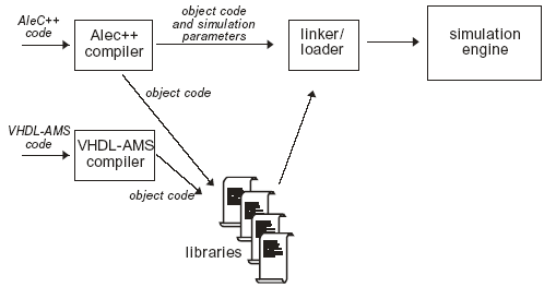
Fig. 5.42: Concept of Alecsis-VHDL-AMS co-simulation
In this chapter we shall demonstrate the possibility of Alecsis-VHDL co-simulation. To realize this idea we are developing a separate program – VHDL-AMS compiler. The most of VHDL constructs are already implemented, as will be illustrated on a simple example.
There are many digital model libraries developed in VHDL, and there are many experienced VHDL users, too. Therefore, our intention is to enable Alecsis to simulate digital systems described in VHDL. It also assumes simulation of mixed-signal systems keeping the advantage of using VHDL standard libraries for description of digital portion of the system.
The simplest way to achieve Alecsis-VHDL co-simulation was to use the existing simulation kernel of Alecsis simulator (virtual processor), and to develop a new compiler suited for VHDL language. Our VHDL-AMS compiler converts VHDL or VHDL-AMS source code into object code for Alecsis virtual processor. Alecsis object code is designed for mixed-mode simulation. Therefore it supports almost all VHDL and VHDL-AMS modeling mechanisms.

Fig. 5.42: Concept of Alecsis-VHDL-AMS co-simulation
Fig. 5.42 shows the co-simulation concept. VHDL source files are compiled with VHDL compiler and objects are stored into simulation libraries. AleC++ source files are also compiled and objects are stored into libraries of the same format. There is only one important difference. Simulation control parameters cannot be obtained from VHDL code. In other words, the root module must be described in AleC++. The simulation engine cannot make difference between library objects obtained from VHDL and AleC++ compiler.
The basic structural unit in VHDL - entity is converted into AleC++ structural unit - module. Each architecture of an entity becomes a new module with the name equal to the name of the architecture. Generic parameters correspond to module action parameters. The data types in VHDL and AleC++ have different names, but the correspondence can easily be established due to the same machine representation. Type real from VHDL corresponds to type double in AleC++, integer to int, records are related to structures, etc. Structural hierarchy is fully supported both in AleC++ and VHDL. It is possible in VHDL description to instantiate components and to call functions described in AleC++ and vice versa. References to those components and functions will be resolved by the linker/loader before the start of the simulation.

Fig. 5.43: An exclusive-OR circuit
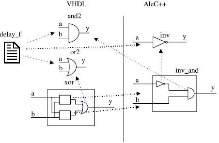
For the illustration of Alecsis-VHDL co-simulation, we shall model a simple circuit shown in Fig. 5.43 with combination of AleC++ and VHDL code. The modeling technique will not be the optimal one, but is intended to be a good illustration of co-simulation possibilities. Fig. 5.44 explains model hierarchy. Inverter (module inv ) is modeled in AleC++. AND circuit as well as OR circuit is modeled in VHDL (architectures and2 and or2 ). Inverter and AND circuit are then combined into the AleC++ module named inv_and . The whole circuit shown in Fig. 5.43 is described in VHDL and named xor2 . The delay delay_f function used both in AleC++ and VHDL is defined in VHDL.
The simulation is performed in 2-state logic system (signals are of bit type). The AleC++ description of module inv follows:

Fig. 5.44: Model hierarchy for circuit from Fig. 5.43
double delay_f (bit, double, double); // func. declaration
typedef enum { '0', '1' } bit; // state system definition
bit const not_tab[] = { '1','0' };
bit operator ~ (bit op) { return not_tab[op]; }
module inv (bit out y; bit in a) {
action (double tr, double tf){
process (a) {
y <- ~a after delay_f (~a, tr, tf) ;
}
}
}
The function delay_f is defined in VHDL. AleC++ only requires its declaration to be visible before the function call, because of type-checking mechanism. Function code is rather trivial.
--- Standard gate delay function:
function delay_f (state: bit; tr: real; tf: real) return real is
begin
if state='0' then
return tf; --fall time
else
return tr; --rise time
end if;
end delay_f;
OR and AND circuits are modeled with the next VHDL code.
--- Two-input AND gate:
entity and2_e is
generic (tr: real := 1.0e-9; tf: real := 1.0e-9);
port (y: out bit; a,b: in bit);
end and2;
architecture and2 of and2_e is
begin
process(a,b)
begin
y <= a and b after delay_f(a and b, tr, tf);
end process;
end inv;
--- Two-input OR gate:
entity or2_e is
generic (tr: real := 1.0e-9; tf: real := 1.0e-9);
port (y: out bit; a: in bit; b: in bit);
end or2_e;
architecture or2 of or2_e is
begin
process(a,b)
begin
y <= a or b after delay_f(a or b, tr, tf);
end process;
end or2;
The block composed of an inverter and an AND circuit (inv_and) is described in AleC++ code that instantiates VHDL component and2. Structural modeling is used.
module inv_and ( bit out y; bit in a; bit in b) {
signal bit inter; // internal signal, inverter output
module inv inverter; // modeled in AleC++
module and2 and_circ; // modeled in VHDL
inverter (inter,a) { tr=1ns;tf=0.9ns;
}and_circ (y,inter,b) { tr=1ns;tf=0.9ns; }
}
The whole circuit is modeled in VHDL and named xor2 . It is composed of two components inv_and and the component or2 .
--- Two-input XOR gate:
entity xor2_e is
port (y: out bit; a: in bit; b: in bit);
end or2_e;
architecture xor2 of xor2_e is
component or2
generic (tr: real; tf: real);
port (y: out bit; a, b: in bit);
end component;
component inv_and
port (y: out bit; a: in bit; b: in bit);
end component;
signal inter1,inter2: bit; -- internal nodes
begin
-- modeled in AleC++
c1: inv_and port map (inter1,a,b);
c2: inv_and port map (inter2,b,a);
-- modeled in VHDL
c3: or2 generic map (tr=>1.0e-9, tf=>0.8e-9)
port map (y,inter1,inter2);
end xor2;
Finally, to simulate exclusive-OR circuit, it is necessary to have a root module in order to define circuit stimulus and simulation control parameters. The following code represents a simple root module for testing the module xor2 by checking its output state for all input vectors.
library "xor";
root module xor_circuit_test (){
signal bit a, b, y;
module xor2 g1;
g1 (y, a, b);
out { signal bit a, b; signal bit y; }
timing { tstop = 30ns; }
action {
process initial {
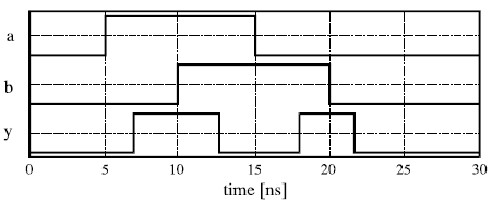
a <- '1' after 5ns, '0' after 15ns;
b <- '1' after 10ns, '0' after 20ns;
}
}
}
Simulation results are shown in Fig. 5.45.

Fig. 5.45: Simulation results for exclusive-OR circuit shown in Fig. 5.43.